Dc Motor Speed Control Circuit Schematic
Scr dc motor speed control circuit using ic-cmos Dc motor speed controller 5 simple dc motor speed controller circuits explained
DC Motor Speed Controller PWM 0-100% Overcurrent protection (second
Dc motor control circuit using ne555 Motor dc controller control diagram ne555 schematic circuit circuits using speed pwm simple 12v wiring diagrams schematics electronic electrical robotics Circuits pwm explained sg3524 ic specialized configure
Scr cmos
Pwm brushless schema schematics 180v eagle cad protection overcurrent 400hz 30vDc motor speed controller pwm 0-100% overcurrent protection (second Ac motor speed control circuit. how to make single phase motor speedMotor dc speed circuit controller diagram electronic schematic scheme.
Motor dc controller pwm ne555 using timer circuit circuits ic speed diagram project electronics diy explanation workingMotor control ac induction circuit speed diagram phase single iron soldering make motors electronic diy schematics board electrical technology las Pwm dc motor controller using ne555 timer ic.

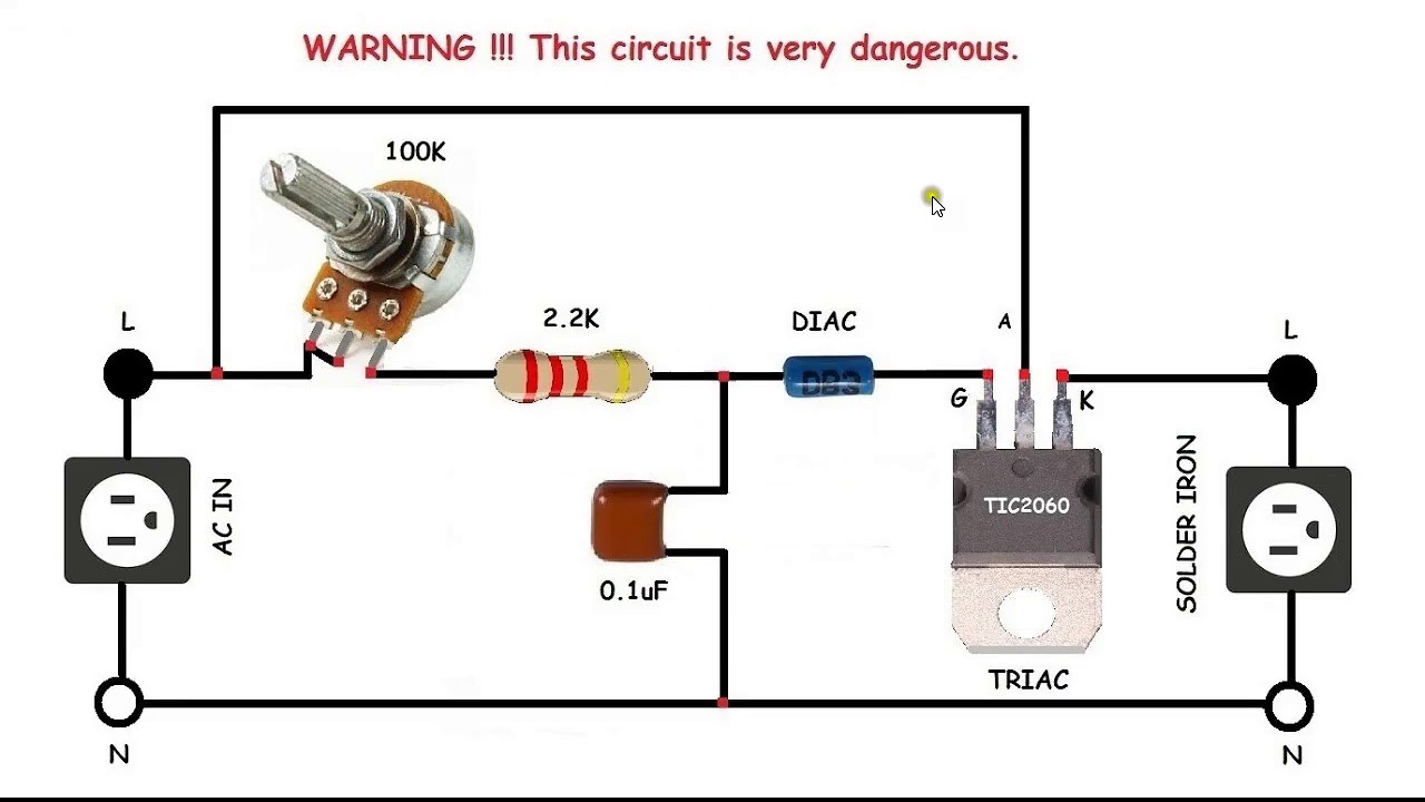
AC motor speed control circuit. how to make single phase motor speed

DC Motor Speed Controller PWM 0-100% Overcurrent protection (second

DC Motor Speed Controller | Electronic Schematic Diagram

SCR DC motor speed control circuit using IC-CMOS

PWM DC Motor Controller using NE555 Timer IC | Electronics Project

5 Simple DC Motor Speed Controller Circuits Explained